Fibre paths
Fibre paths affect mechanical performance.
The mechanical performance of composite products highly depends on fibres. The orientation of the fibrous reinforcement mainly determines the directionally dependent strength and stiffness of the part. The fibre directions of an initially flat laminate change during the forming process due to the change in geometry of the blank and its in-plane deformations such as intra-ply shear. It is important to describe the fibre orientations accurately in order to obtain a reliable expression/prediction of the product’s stiffness and strength. AniForm is able to predict the developing fibre paths introduced by the forming process.
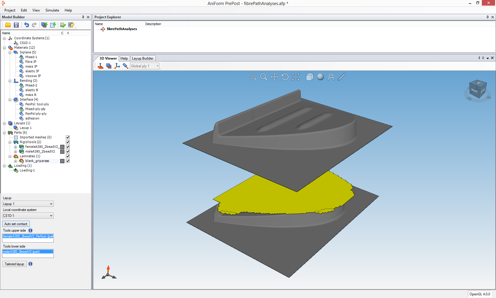
Figure 1: AniForm PrePost screenshot showing the tooling (grey) and the blank (yellow) to be formed.
Wing stiffening ribs used in aerospace industry require accurate predictions of their mechanical performance as these are part of a large load carrying structural assembly. This structural component is modelled in AniForm PrePost in figure 1. A simulation was set up in order to obtain the fibre paths after forming. A layup was assigned to the blank, which describes the material's constitutive behaviour during the forming process. The blank contains four quasi-isotropically stacked layers, each having two families of fibre directions.
Figure 2: Animation of the predicted forming process.
The simulation was started after defining the position and the movement of the tooling, resulting in the forming prediction in figure 2. Figure 3 shows the predicted fibre paths of one family of fibres in the top ply. These data are available for all modelled plies and family of fibres. The fibre paths significantly determine the part’s response, while it is in service. These fibre paths can be affected by changing the modelled process parameters, such that the optimal process settings can be searched for with the aid of multiple process simulations.
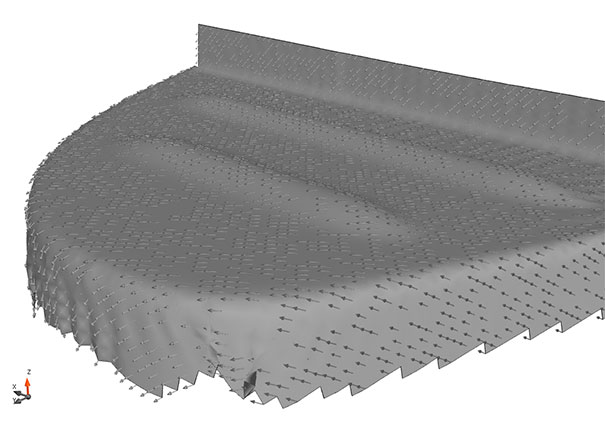
Figure 3: Predicted fibre paths of one family of fibre directions in the top ply of the blank.
Currently, an exporter module is in development, which allows you to export the predicted fibre paths to other FEM software. Please contact us if you would like to have more information regarding the export formats and compatibility with the FEM software for structural performance calculations. On request, our engineering service offers the export of forming prediction results in the required format.
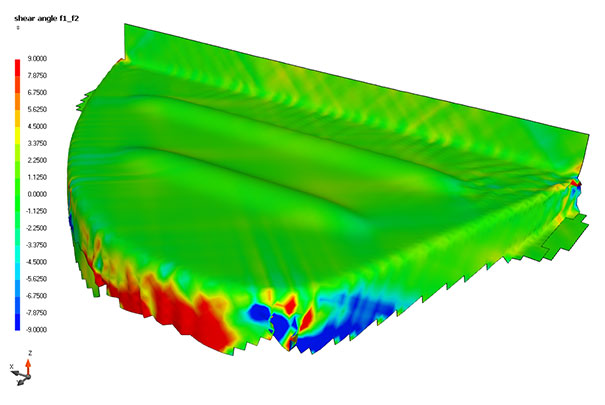
Figure 4: Predicted shear angles in the top ply of the blank.
Intra-ply shear often accompanies a change in fibre directions, which is shown for the top-ply in figure 4. The shearing reaches a maximum at the front of this part, resulting in a large wrinkle. Large wrinkles can lead to fibre breakage in the blank and damage of the tooling. The position and size of such a wrinkle can also be optimised by running multiple simulations with different process settings.
Experimental validation of simulations has been done for a couple of cases, which can be found in [1-6]. This wing stiffening rib was investigated in a slightly different setting, as can be read in detail in Haanappel [1].
[1] Haanappel, S.P. Forming of UD fibre reinforced thermoplastics: a critical evaluation of intra-ply shear University of Twente, ISBN: 978-90-365-3501-4, 2013.
[2] B. Rietman, S.P. Haanappel, R.H.W. ten Thije, and R. Akkerman. Forming simulation sensitivity study of the double-dome benchmark geometry. The 15th International ESAFORM Conference on Material Forming, Erlangen, Germany. In Key Engineering Materials, volume 504-506, p301-306, 2012.
[3] U. Sachs, S.P. Haanappel, B. Rietman, R. ten Thije, and R. Akkerman. Formability of fiber-reinforced thermoplastics in hot press forming process based on friction properties. The 16th International ESAFORM Conference on Material Forming, Aveiro, Portugal, 2013.
[4] R. ten Thije and S.P. Haanappel. Multi-layer thermoplastic composites manufacturing processes: simulations and experiments. SAMPE Europe International Conference & Forum (SEICO 2011), Paris, France, 2011.
[5] R.H.W. ten Thije and R. Akkerman. Finite element simulations of laminated composite forming processes. The 13th International ESAFORM Conference on Material Forming, Brescia, Italy. Conference proceedings, 2010.
[6] S.P. Haanappel, R. ten Thije, and R. Akkerman. Forming predictions of UD reinforced thermoplastic laminates. 14th European Conference on Composite Materials (ECCM-14), Budapest, Hungary, 2010.